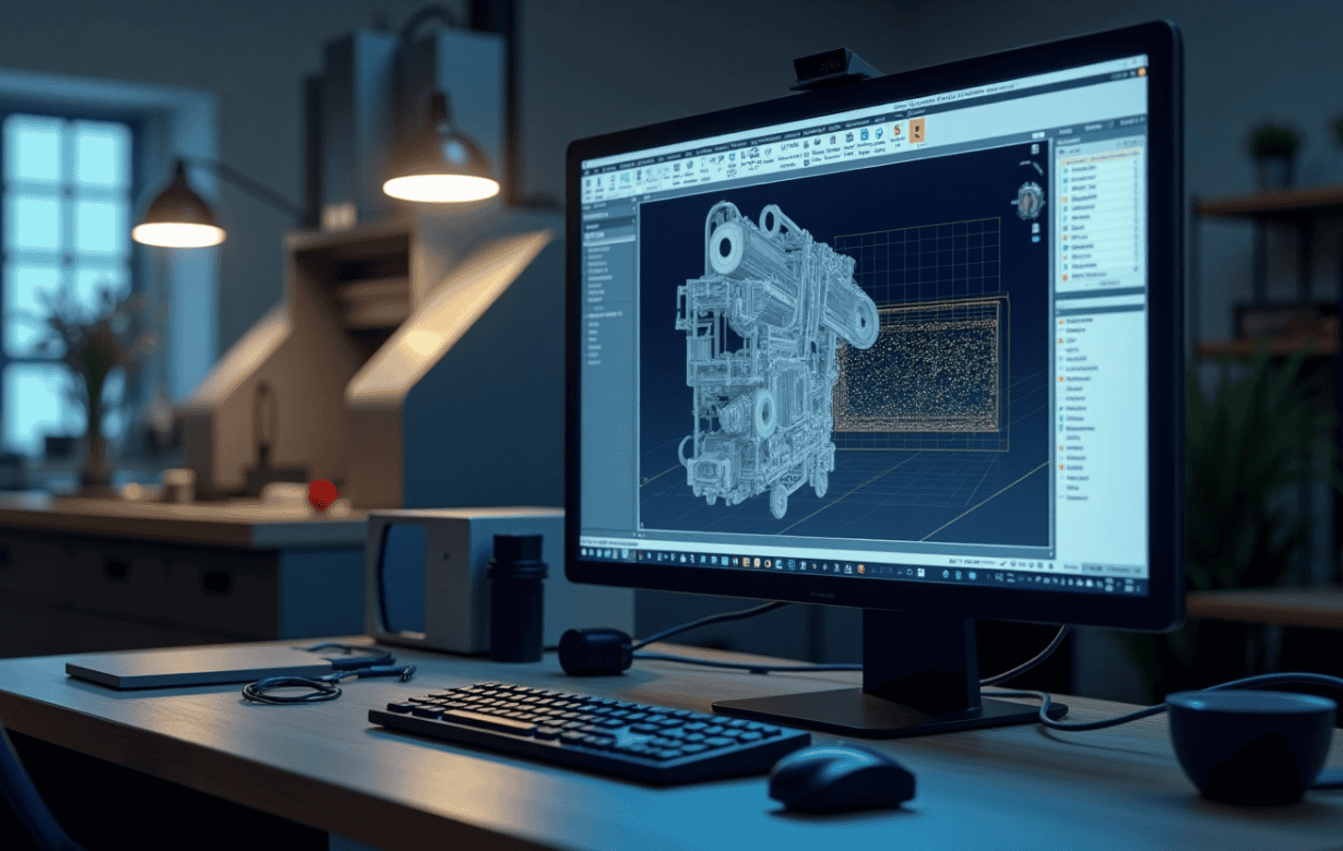
How do I convert a CAD file into G-code?
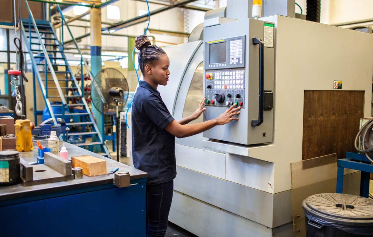
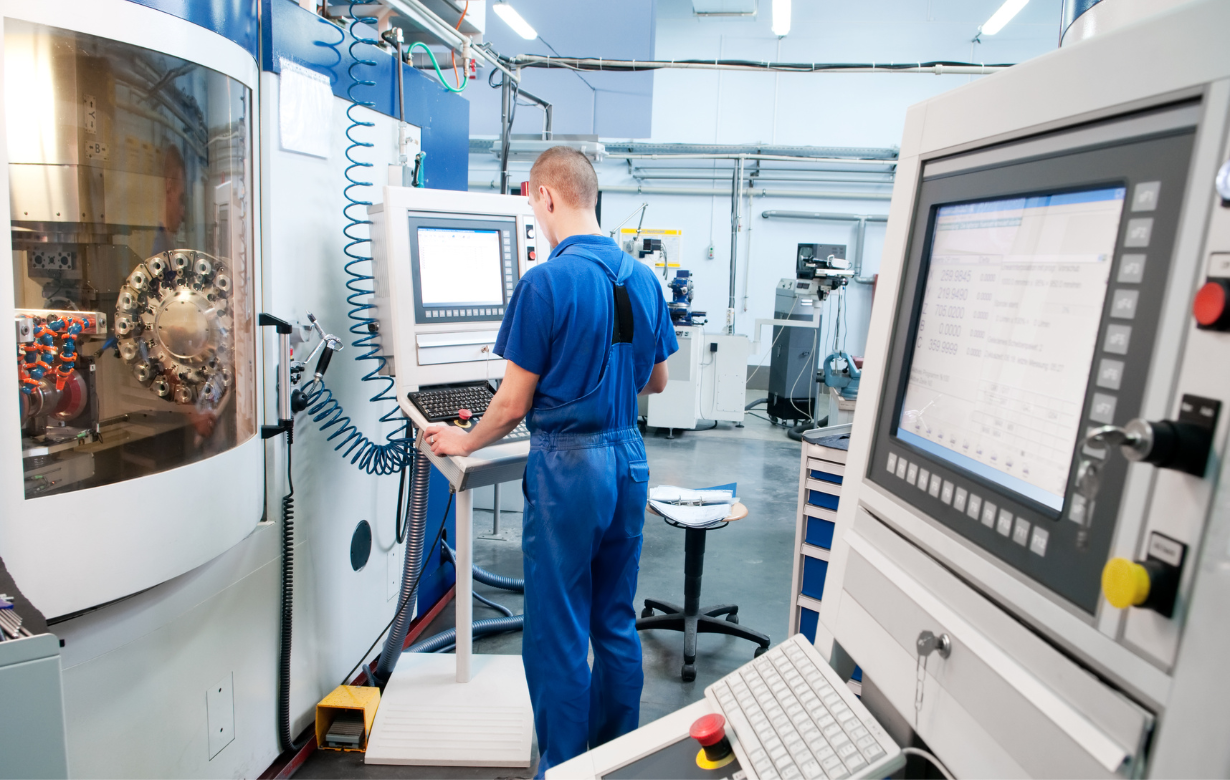
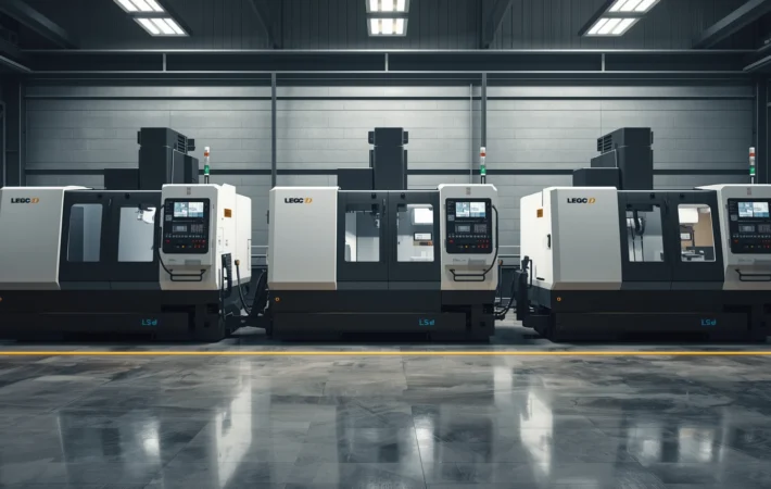
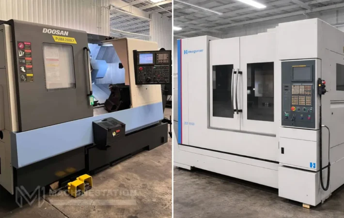
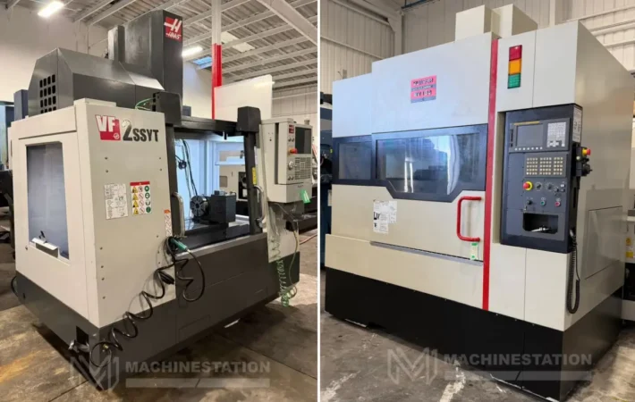
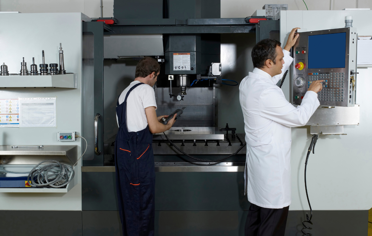
CNC machines are used for developing different kinds of complex structural products of different materials like steel, aluminum, and wood. CAD or Computer Aided Design software helps you to create a digital prototype of the final product that you wish to create with the help of the CNC machining process. To help the CNC machine execute the necessary moves to make the desired product one will have to convert the CAD file into a G-Code, which is a program that instructs the CNC on how to move and in which direction to move to complete the machining process.
Understanding CAD and G-code
Before we dive into knowing how to convert the CAD file into G-code, first let us find out what CAd and G-code mean:
CAD Files: These are the digital blueprints of your design but they lack machine-specific designs. They contain geometric information about the part, like its dimensions, features, and shapes. The most common CAD files include.STEP, .IGES, .STL, .DXF, .DWG.
G-code: This is the programming language that the CNC machine can understand. This is basically a series of alphanumeric commands that help in guiding the different movements of the machine. Each line of the code is used to specify any particular action.
Software requirements
To convert the CAD files into G-code you will need some software and here’s a list of the software you can use:
- CAD software: This is where you can create the design of your final product. Popular CAD software options include SolidWorks, SketchUp, Fusion 360, and Autodesk Inventor.
- CAM software: This software will do the main job of converting the CAD files into G-code. Some of the most famous CAM software are Mastercam, VCarve, Aspire, and CAMotics.
Steps to convert the CAD file into G-code
Now, here are the steps that you will have to follow to convert a CAD file into a G-code easily:
- Prepare your CAD file: In the first step, you should work to prepare the CAD file, and you need to ensure some things like – the design is free of errors, there are no unnecessary features and it is scaled to the desired units.
- Choose your CAM software: In the next step after preparing your CAD file you will have to choose your CAM software as per your operations requirements.
- Import your CAD file: Once you are done selecting the CAM software necessary for the machining works, you will have to insert the CAD file and do the calibrate scaling by using a reference line in the design to match the real-world dimensions.
- Setup your CAM software: In the next step you will have to configure the CAM software by – selecting the machine you will be using, specifying the material properties like its thickness and type, and selecting the tool that you will be using.
- Generate toolpaths: Then you will have to create toolpaths that define the machine’s movement which includes – 2D or 3D milling for milling machines, drilling for drilling operations, and laser cutting for laser cutters. Then you need to configure the toolpath settings like – feed rates, spindle speed, and depth and pass settings.
- Simulate and verify: You should just do a trial to verify that the machine is following the right path, collisions are being avoided, and material removal is accurate.
- Generate the G-code and post process: Once the verification of the toolpaths has been done then you will have to go ahead with the generation of the G-code. Then the CAM software will translate the toolpaths into a G-code file. Then you will have to select a post processor for your CNC machine which generates a plain text file typically with a .NC, .TXT, or.GCODE extension, containing all the G-code commands.
- Export and run the G-code: In the final step, you will have to transfer the G-code to the machine’s control system. This export can be done using USB, ethernet, or direct serial connection.
Common errors and method of troubleshooting
Error | Cause of error | How to solve the error |
Scaling inaccuracies | Incorrect reference dimensions | Recalibrate using a known measurement. |
Toolpath jumps or gaps | Open vectors or broken geometry | Repair CAD geometry before conversion. |
Machine compatibility issues | Wrong post-processor | Use machine-specific settings (e.g., GRBL for DIY CNCs). |
Syntax errors | Unsupported G-code commands | Validate code with simulators like CAMotics |
Conclusion
In conclusion, converting your CAD file into a G-code is one of the most important methods in your whole machining process. The conversion method is not that tough and can be done by following the steps we mentioned above.
If you are someone who is planning to buy used CNC machines, then you can check our collection at MachineStation. If you can’t find the right fit there, then let us know your requirements in the Machinery Locator and we will try to help you out.